Reviewed by Editor: Jack Allison
VIDEO_01[ENG] VIDEO_02[ENG] VIDEO_03[ENG] VIDEO_04[ENG] VIDEO_05[ENG]
Related experiments:
- Raspberry-pi: Experiment 13. Anemometer based on sensors f200-2012
- Raspberry-pi: Experiment 13. Thermal sensor and more
- Raspberry-pi: Experiment 13. Few more experiments with batteries
- Raspberry-pi: Experiment 13. Anemometer. Less power consumed more produced and preserved
Experiment Goals:
1. To learn how to connect the wind-direction and wind-speed sensors so that reasonable signals will be generated as a reaction to sensors’ rotation.
2. To Enable reading and analysis of the sensors’ signals
3. Connect all the anemometer parts and pack everything to a hermetic prototype for outdoor observation.
Components:
Electronics:
– Raspberry Pi Model A+ (ebay)
– EDIMAX Wi-Fi Adatper (EW-7811Un (ebay))
– (2x) 1W 5V 180mA Solar Power Panel, 99 x 69mm (ebay)
– (2x) SS34 diodes (ebay)
– (1x) ADC Pi V2.2 8-channel A2D converter from www.abelectronics.co.uk for reading the battery voltages
– (1x) Wind Speed Sensor – spare part for weather station (ebay)
– (1x) Wind Direction Sensor – spare part for weather station (ebay)
Mechanics:
– (1x) Empty chocolate box of medium size form Ferrero Rocher (ebay)
– (2x) unused parts of adjustable furniture legs (left from IKEA furniture) serving as stands for the sensors
Rechargeable batteries (connected in parallel):
– (8x) rechargeable batteries AA 1.2V 3000 mAh (ebay)
– (4x) New Sun-PL653494 7.4 V 1800mAh (ebay) betteries
– (3x) Unknown rechargeable batteries (from “Move Power”)
Use-Case:
1. No external power for a long time
2. No physical access for a long time
3. No Wi-Fi + Internet infrastructure in near proximity
4. Anti-theft GPS module (optional)
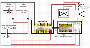
Architecture: The diagram below shows the desired architecture. In this experiment Wi-Fi is used instead of GSM and the GPS module is not connected. However, the capabilities of GSM communication and reading location and time with the GPS module were enabled at previous experiment. There is a plan to connect them in the final prototype.
Schematics:
Software:
https://github.com/pageal/RPi-Wind.git
Pictures and Stories:
– The prototyping process was preceded by a few experiments related to battery array strength and charging cycle. Results indicate that additional current is required from solar panels, thus more of these were ordered. When connected, they should provide about 1Ah (instead of 360 mAh now). So far the pack without any sensors survived alive about 48 hours transmitting its status.
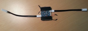
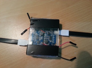
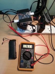
-This charger is built from the two circuits remaining from the “Move Power” products taken apart in an earlier experiments. Thus, all the spare parts (except the case) from two bad-functioning devices were re-used.
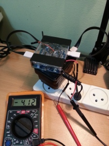
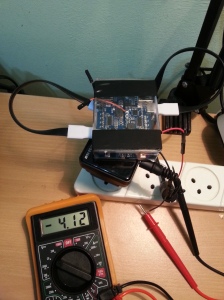
– While connected to two USB ports, this charger allows simultaneous charging of two accumulators to 4.12V. However, building of cables which allow direct connection of these accumulators to a USB splitter would allow simultaneous charging to 5V. Thus, this is in the plan. After the cables are built, the recharging cycle should shorten as there will be no need for several charge balancing sessions (when weaker accumulators charge from stronger ones). At least one such a session is necessary now to bring the battery array to about 5V.
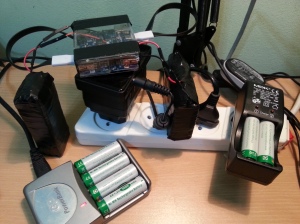
– These are all the chargers working together for the purpose of charging the entire battery array before prototyping can start.
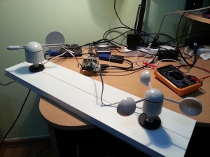
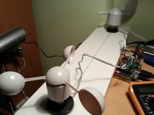
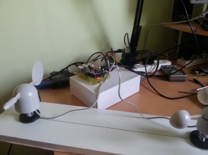
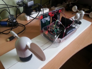
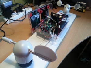
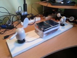
– The prototype was created mostly by using epoxy to glue together various pieces of the fixture. If necessary, the sensors may be unscrewed from the fixture. As a specification of the sensors was missing, several experiments were conducted to understand proper connectivity. The wind speed sensor appeared easier to understand as it has only two wires. The mystery of the wind direction sensor wasn’t cracked until this link was found with a schematics which described the connections between components. It was hard to imagine the black wire, which usually goes to ground, connects to VCC as does the red wire (but through a 10KOhm resistor).
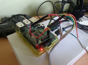
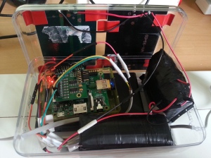
– Here is the final interconnection, described in the schematics earlier in this post.
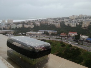
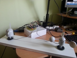
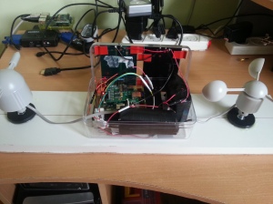
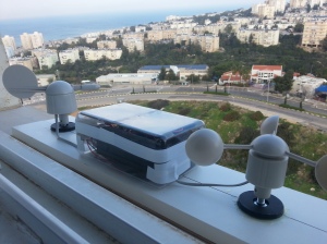
– Working prototype with RPi in its waterproof case.
Useful links:


Pingback: Raspberry Pi Experiment 13: Anemometer based on sensors F200-201/2 (wind speed/direction) | My Hobby of 'Making'
Pingback: Raspberry Pi Experiment 13: Few more experiments with batteries and order in wires | My Hobby of 'Making'
Pingback: Raspberry Pi Experiment 13: Anemometer. Less power consumed more produced and preserved | My Hobby of 'Making'
Pingback: Raspberry Pi Experiment 13: Thermal sensor and more | My Hobby of 'Making'
Pingback: Raspberry Pi Wind Measurement | Hackaday
Pingback: RASPBERRY PI EXPERIMENT 13: Anemometer based on sensors F200-201/2 v2 | My Hobby of 'Making'