Project Idea and Requirements by: Masha Lipshits
Goals:
– to learn using Arduino uC, relay and motion sensor
– using Arduino Pro mini, to make our corridor lamp automatically switching ‘On’ if motion is detected in the area of the entrance-hall. Switch ‘Off’ – by timeout.
– finally installed prototype shall be extendable (ex. by RF components sending motion detection to central PC) and allowing easy and safe maintenance and upgrade.
Note: As a result of this post being reviewed and discussed at Hackaday, I’d like to note (thanks the reviewers) that using Arduino in this experiment is NOT necessary, as the project was not finally extended with RF transceiver as planned. RF transmission of “LAMP-IS-OF” activated IR sensor and turned the lamp back ON, and lack of time were making me finishing this experiment in the middle. Thus, the not is as following, again: for just lamp switch on-off solution Arduino is actually not necessary. The reason is a presence of “Time Delay Adjust potentiometer at HC-SR501 Motion Detection sensor used here, which sets how long the output remains high after detecting motion (anywhere from 5 seconds to 5 minutes) so that it may be used for driving of the enable pin at the relay.
Components:
– HW: Arduino Pro Mini’s clone Funduino
– HW: Relay (one relay is enough, but I had only two-channel relays) Theory
– HW: Motion Detection sensor
– HW: 220V->5V AC to DC converter (taken from old power supply)
– SW: sketch
– Mech: old plastic box
– Mech: spare Raspberry-Pi camera case (for motion detection sensor)
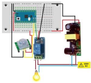
Wiring:
Description:
– Learning to use Arduino lead to creation of the appropriate ‘Getting-Started’ page
– Then was a turn to try and use relay with Arduino GPIO.
– motion detector also was connected to another GPIO pin configured to be treated as input.
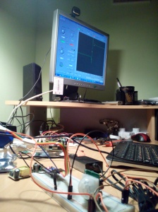
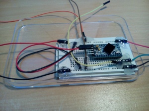
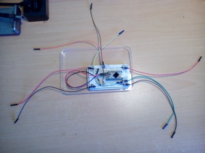
– after enabling of the components, bread-board based complete prototyping and after completion of the Arduino SW sketch, there stage of final assembling begun.
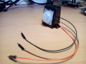
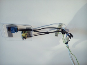
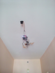
– motion detector sensor was placed into special case which will allow to install it at some distance from the switching module and the lamp itself so that the sensor will provide sufficient coverage of the entrance hall and will not react on motion at the adjacent guest-room
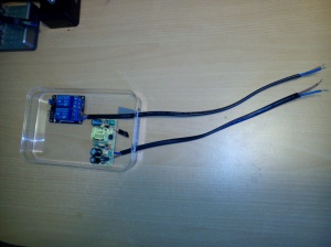
– AC-related components were attached to the top cover of the box and connected to the 220V AC source
– then digital components and wires were prepared at the bottom cover of the box
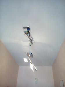
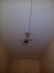
– then all was assembled in place and sealed.
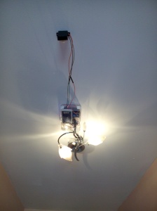
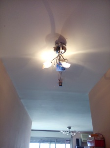
– all appears to be working as expected
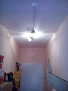
And here how the final product looks like


