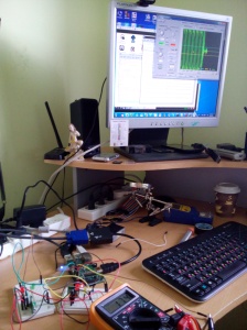
Goal: Learn using RF 433Mhz with SMAKN Amplitude-Shift-Keying Tx/Rx Kit
Components:
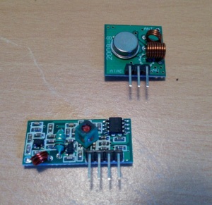
– SMAKN 433MHx Transmitter and Receiver modules (ebay) (scarce data is downloadable)
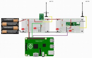
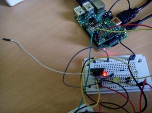
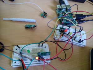
– RPi and its GPIO pins
– Tool: http://www.zeitnitz.eu/scope_en described also here
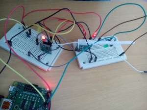
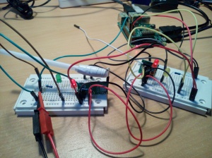
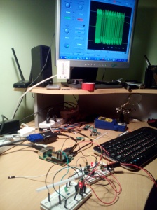
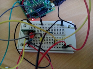
Wiring:
SW:
– Virtual wire from here by abyz with a bug fixed by me (the tx gpio pi wan’t set to 0 after transmission completion thus a sometimes lots of strong noise was observed at the receiving side).
This utility code uses pigpio module also from abyz
Conclusions:
– Even bad scope gives eyes when dealing with signals and especially RF
– In case of this SMA RF kit at least one antenna is essential (either at transmitting or receiving side) to improve signal strength (and consequently signal to noise ratio – SNR).
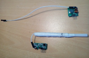
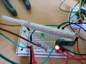
– Receiver has small coiled antenna soldered on it. The antenna we add just extends the default antenna coming with the module. The expanded antenna also amplifies noises. Thus, spoken of signal-to-noise-ratio (SNR) , it appears to me to me (based on this experiment) that the best configuration with these modules is: straight-wire antenna at the Transmitter and default antenna at the Receiver.
Experiment Description:
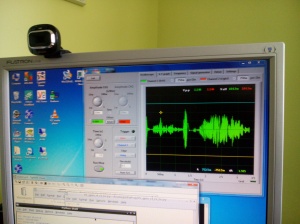
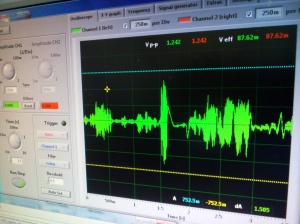
– this is a constellation with antennas at both sides transmitting and receiving: transmitter – 21sm of straight wire, receiver – 36sm of wire coiled into 3.5sm long antenna
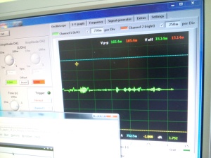
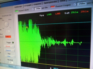
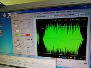
– DATA pin sensed at the receiver
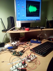
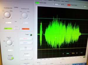
– DATA pin sensed at sender. I’ll never sense this pin anymore at this experiment. At all the antenna constellations I sent the same data and the signal is always clear and strong as it is sensed before modulation and distortion in radio.
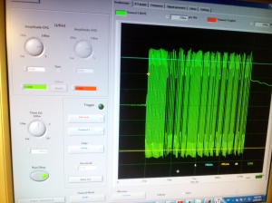
– this how noise looks at the receiver side when data pin is forgotten to be cleared to 0 at the sending side
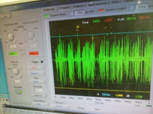

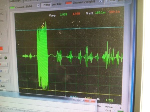
– this time antenna at the receiving side was expanded to 72sm of coiled wire forming 7sm antenna; transmitter still having an antenna of 21sm of straight wire
– this time sending side has no antenna, while receiving has 7sm of coiled wire
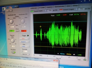
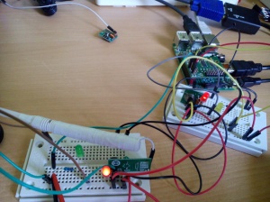
– here the receiver has no antenna while sender’s antenna is 21sm of straight wire
the noise at the receiver:
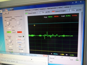
– now how it looks without antennas at all. Data signal at both pictures looks much more distorted and having lower amplitude. In both the case the data packed was not received at the end, while it was received with configurations having some antenna at least at one side
Related Links:
– How to control power outlets using RPi/Wireless power outlets
– Wireless RF links and noise reduction tutorial


