


Reviewed by Editor: Jack Allison
Today day was mostly filled by soldering among other activities such as traveling with family etc. 🙂
Improvements:
– Raspberry Pi model A+ (instead of model B) which is smaller, consumes less power, has one USB instead of two, and a micro-SD slot instead of a regular SD-card slot.
– New (smaller, lighter) voltage converter: 220-12V
– Converter 12 V -> 5V x 2 (3 A): 5V – for RPi power, 5V – for cellular dongle spare power (further extension). This reduces two external converters 220V->5V and 220V->12V (for the array of IR LEDs) to a single external converter 220V -> 12V (one power cable to camera). Of course there is 12V->5 converter instead but it is located internally within the case (in my eyes, more elegant solution).
– Large plastic bread-board is replaced with smaller prototyping board and soldered down parts.
– All connectors now detachable, allowing better maintenance. This required making custom length wires and attaching appropriate connectors.
Related experiments:
- Video streaming (WiFi)
- Video streaming (cellular network)
- Video streaming (HTTP)
- Video streaming (Web)
- Adaptive streaming (VLC)
Achievements:
– Overall smaller size of internal components.
– Improved Maintainability .
– Having several RPi board allows me to keep several prototypes working simultaneously without a need to detach a board from a prototype for side experiments.
– Auto-initialization (on power-up) of camera’s WiFi-interface enabled today. This allows work on Camera SW with closed case.
A few pictures from today:
– The following four pictures show how the larger bread board is replaced with a smaller prototyping board and soldered down parts. This freed more space within the case. Also the connectors visible from the side allow easy detaching when necessary.


– The picture below shows the smaller RPi A+ board which allows more optimal usage of the space within the case and pushing the 12V->5V converter inside. Also we see spare USB female-connector going from the converter – preparation for plugging of cellular dongle’s spare-power side of Y-cable. Together with USB splitter (that is to buy yet) this will allow cellular model (with backup power) connected in parallel to Wi-Fi.
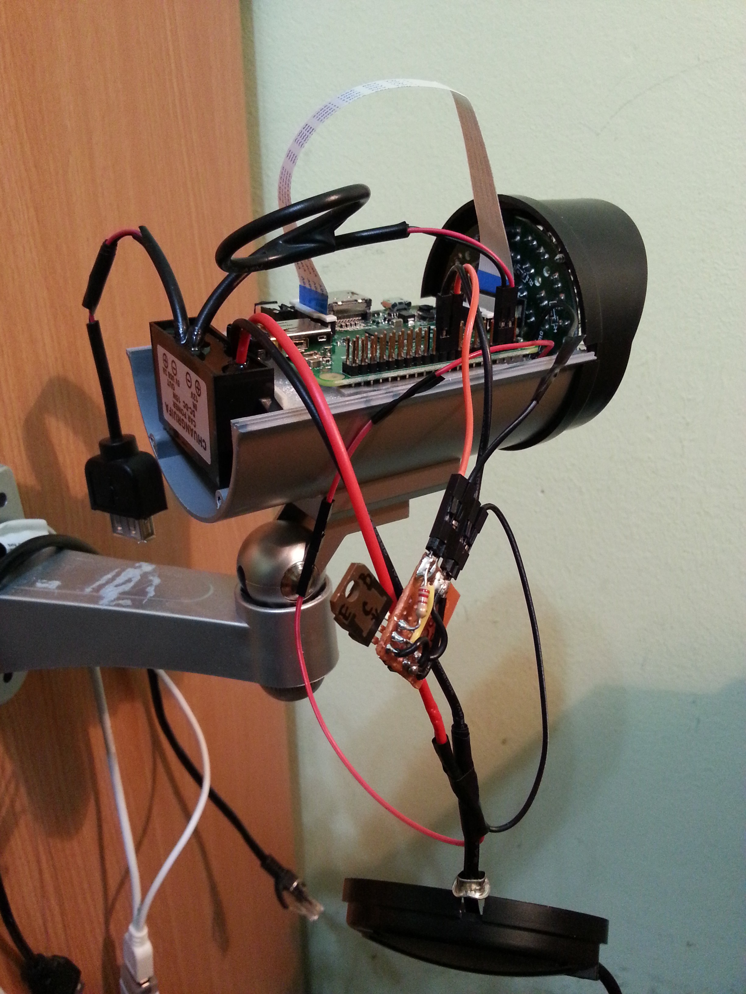
– The next picture shows components almost ready to be put in the case. After adding additional wires for the IR array, and more wires were prepared, the components were put into the case. Already here this may be seen that from the two power adapters 220V-12V and 220V-5V only 12V remained.

– This photo shows the wire preparation process from components bought separately: wire, metal and plastic part of the connector.

– The following pictures show how accurate the camera looks with only one brand-new 220V-120V smaller adapter and consequently only one power cord running to the camera. RPi’s logo on the first picture means that the camera is powered up. Subsequently, I have tested the streaming SW and all functionality appeared to be working as before today’s changes in HW.


Good job! 🙂
Thanks, darling! Also for being patient and understanding
I noticed your website’s ranking in google’s search results is very low.
You are loosing a lot of traffic. You need hi PR backlinks to
rank in top10. I know – buying them is too expensive. It is better to own them.
I know how to do that, simply google it:
Polswor’s Backlinks Source
I don’t treat my blog as commercial yet so I didn’t invest there. But, thanks for your advice, I’ll check the links that pop-up from the proposed google-search. 🙂
Pingback: Raspberry Pi Experiment 13: Thermal sensor and more | My Hobby of 'Making'